Fan Noise Reduction of HP Procurve 2650 Switch
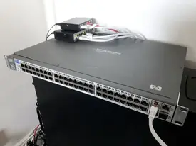
In the earlier post I mentioned noisy fan of my recently bought HP Procurve 2650 L3 Switch. Today, I have a solution to the problem.
Actually, noisy fans seem to be quite common in rack/server room targeted network devices (switches, routers). According to my observations, the problem covers Cisco Catalyst 2960-S switches, as well. This is a major problem if any of these switches are installed at otherwise silent office or school environments.
There are basically two methods to work around the noisy fan problem.
Table of Contents
Why are switch fans so damn noisy?
Main issues which produce a lot of noise in switches are generally:
A) resonance between switch case and attached fans: switch manufacturer may have left out proper fan isolation. It is just a metallic switch case and hard plastic fan bodies
B) high fan spinning speeds, combined with the resonance problem A)
Solution: Just taking out switch fans?
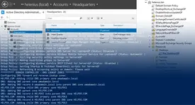
If you ever considered just taking out your switch fans without further steps, be aware: you likely end up to have a switch filling its event logs with entries of faulty fans and having a blinking fault light on the front side of the switch. Unless you can modify the switch firmware (operating system binary file) you are not able to circumvent this programmatic problem.
Basically, switches continuously monitor fan statuses and if they see any failures such as reduced RPM fan speed (or detached fans), they consider this fan to be faulty and to be replaced by a new (working) one.
Main issue here: you still want reduce the speed or even take out noisy fans. It is possible. I introduce two alternative methods below.
Feed fake RPM signal to your switch?
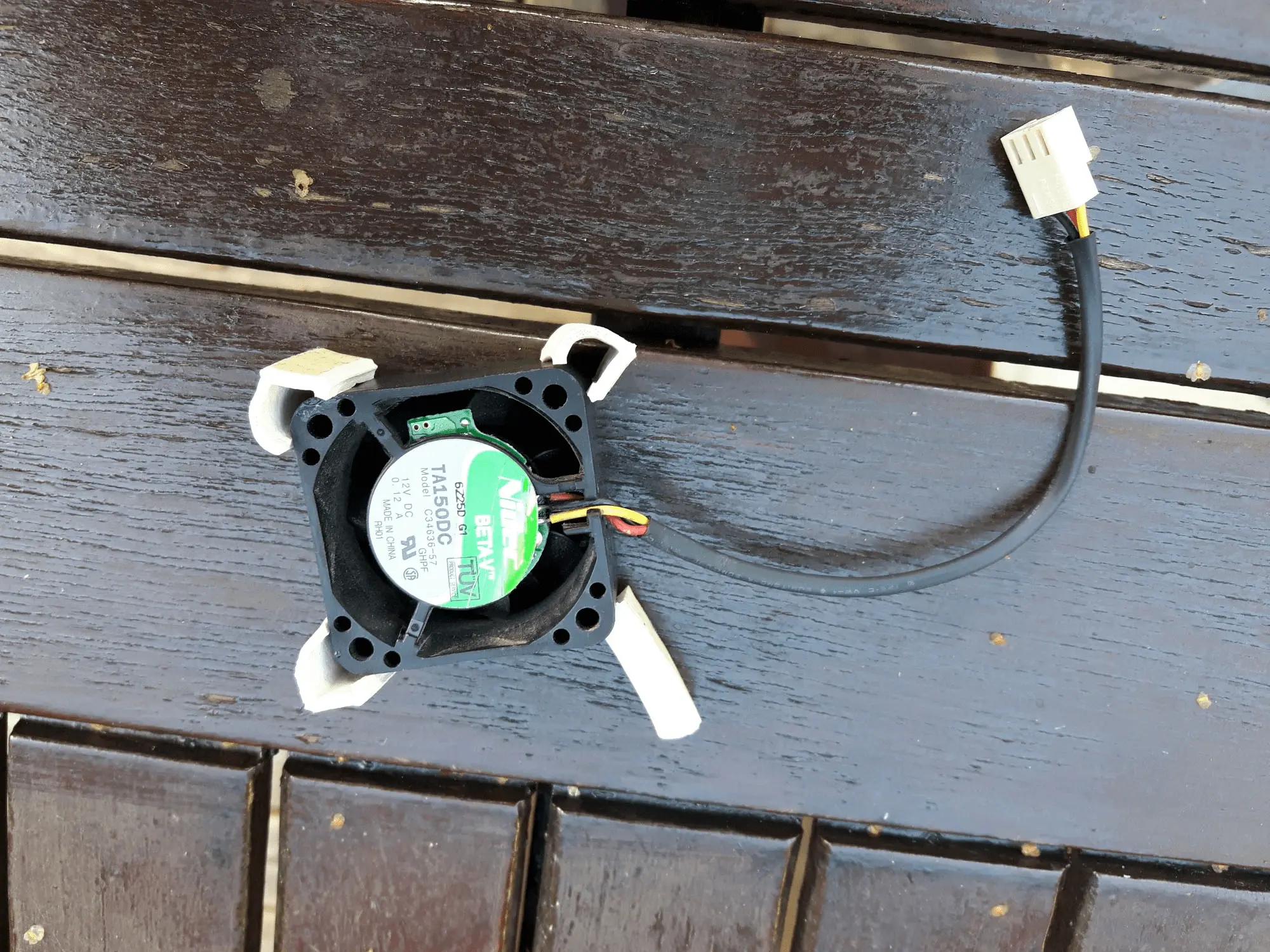
The first method is to apply a fake tachometer signal simulation/square wave pulse modulation, and either using more silent fans or taking the fans out altogether. Switches usually use a common 3-pin PC fan socket and their embedded operating system usually check status of the fans from the tachometer (RPM) signal, generated by the attached fans. Tachometer signal is transferred via an outer yellow/white wire in PC fan installations.
This method could be used in many switches. However, before implementing anything, you should know what your switch actually measures here:
A) Does your switch actually measure and expect the RPM signal?
Take out a switch fan and attach it to a normal desktop computer. Check out the RPM value given by the fan.
If the RPM signal is N/A, it is likely that the fan does not report tachometer (RPM) signal, so you know that your switch does not check the actual RPM signal since the fan does not generate any.
If the RPM signal is not N/A, write down the fan RPM value. This is the value you must emulate/fake for your switch, since any other value may be considered faulty by the switch.
B) Does your switch measure and require a specific voltage level for tachometer socket pin?
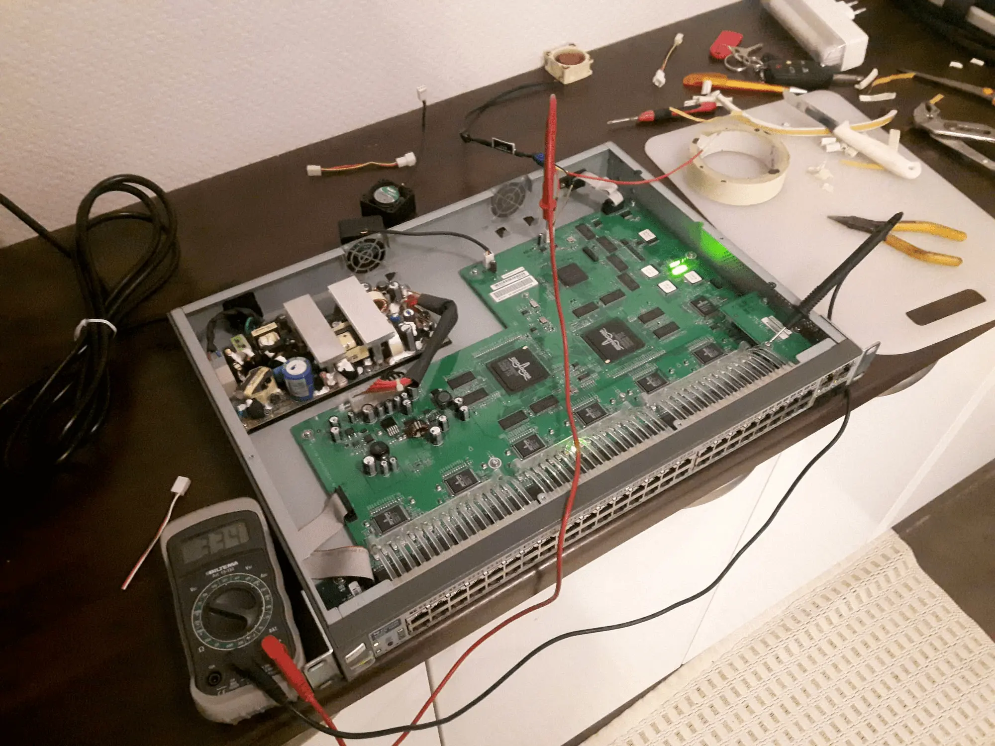
If your switch does not check RPM signal level, you should measure the actual current and voltage levels of the tachometer pin while the switch is powered on and the original fans are attached & spinning normally. Write down the values, and use them as reference for further use.
For instance, tachometer pin voltage levels of HP Procurve 2650:
Original fan used: 0.03V (normal fan code generated)
A fan which reports 3000RPM signal: 1.66V (faulty fan code generated)
No fan: 3.33V (faulty fan code generated)
Usually, RPM signal is measured (at least in Cisco switches) but in my HP Procurve switch actually the voltage level seem to be the more relevant. HP Procurve 2650 original fans (40x40x20mm) does not produce any sensible RPM signal. I tested this on another computer, which simply printed out RPM value N/A.
If you can confirm your switch fans actually report speed data back, you should take a look on the following links. There are guys who have faked fan RPM signal successfully in several switches:
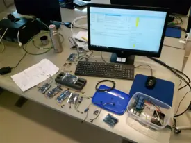
In my first attempt, I followed these instructions and successfully built a “fake fan RPM sensor” (method A above). I did a short analysis (electricity measurements) and the fake sensor actually worked. However, since the method does not apply to the HP Procurve 2650, I abandoned the sensor from my final installation and proceeded with the second method I introduce below:
Apply more noise isolation to your switch + reduce fan speed?
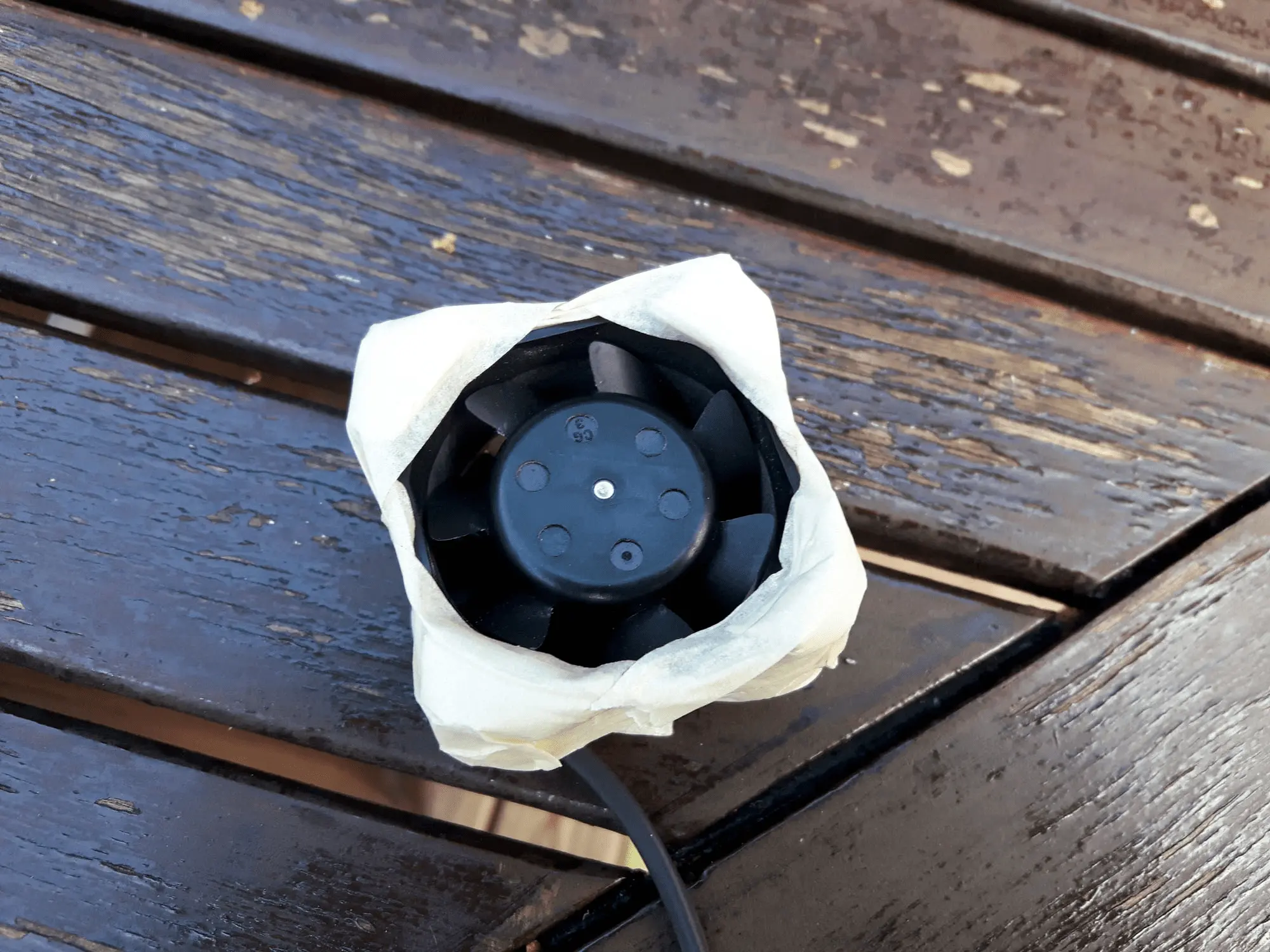
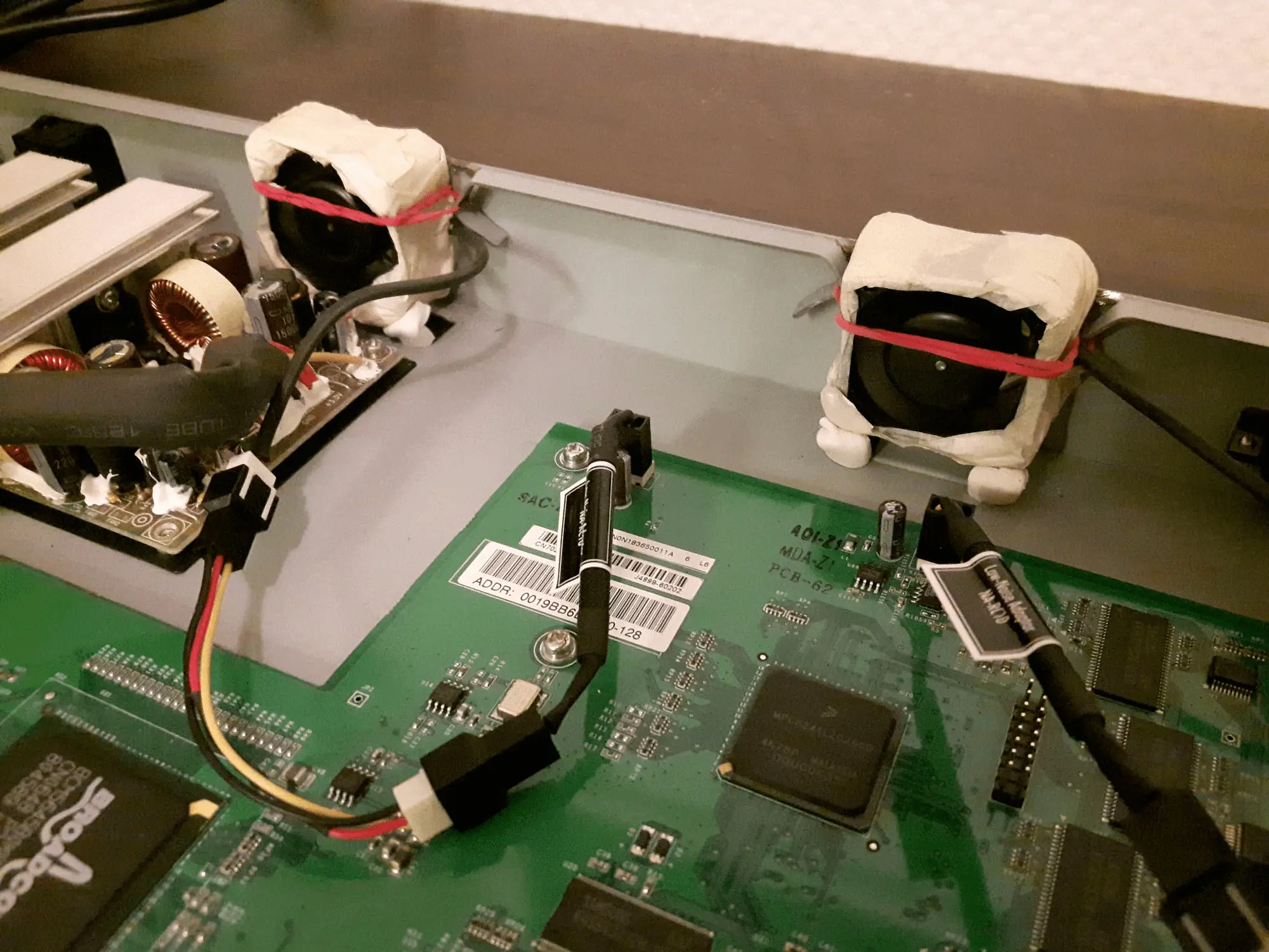
The second method is to apply more noise isolation between fans and the switch case. This significantly reduces resonance produced by fast spinning fans. In terms of complexity and implementation difficulties, this method is more simple to apply in existing switch installations.
However, major downside is that you may need to physically modify the switch case, and thus say goodbye to any warranty. So, use a cheap and old switch if any physical modifications must be done. For instance, my HP Procurve 2650 was a very cheap switch so I wouldn't trouble myself or hesitate if small modifications should be carried out.
Additional step to the proper isolation between the switch case and fan body is to reduce fan RPM speed if possible. This is very easy step as you only need to add more resistance to the 12V fan power cable (usually red-colored). You can't use limitless amount of resistance, however, because the switch fans must be able to spin up during switch booting phase. Simply add a new resistor to the power cable and you're good to go.
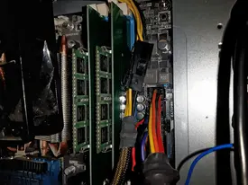
The following pictures show briefly the steps I took:
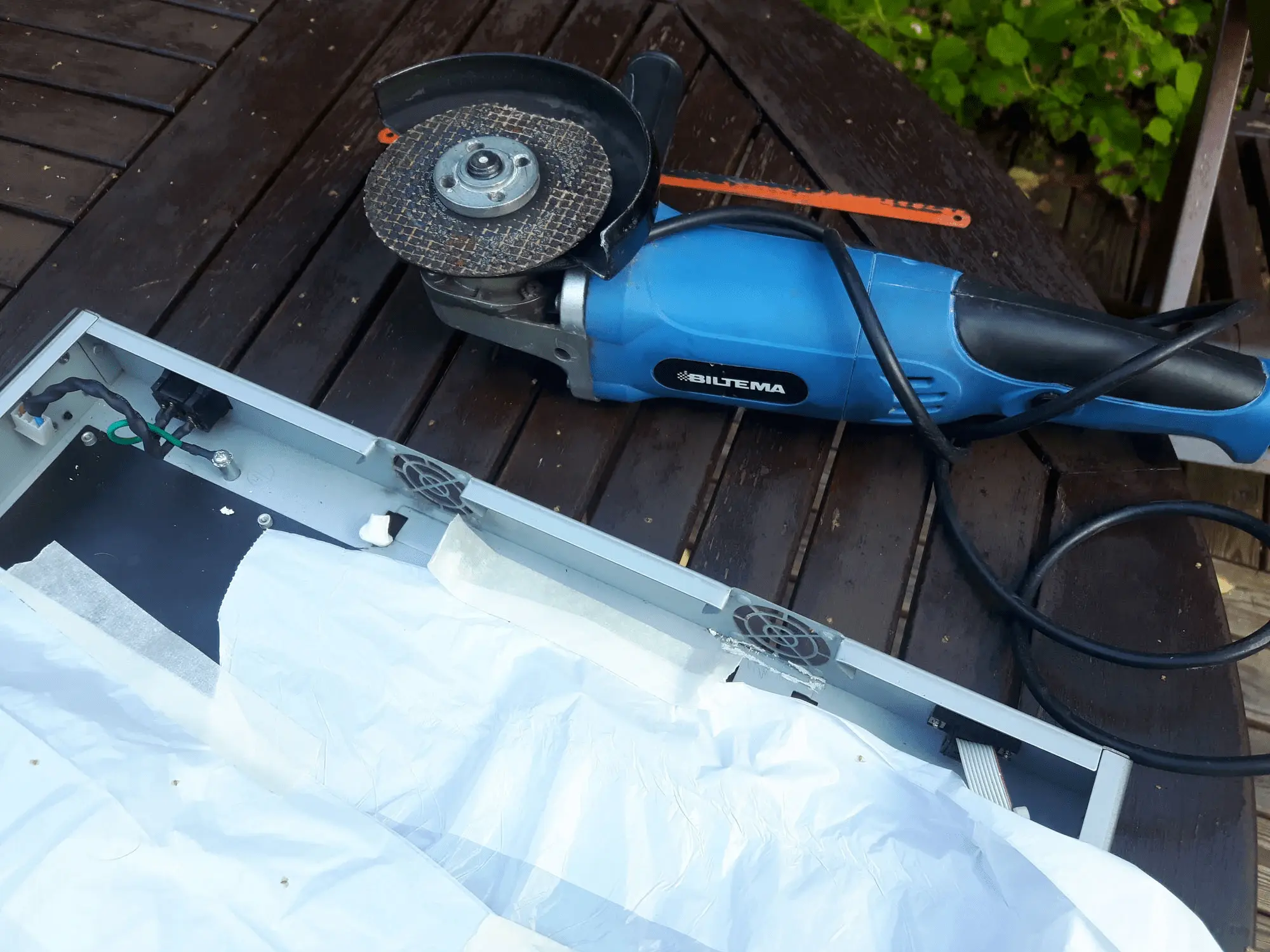
BE AWARE: do not apply any grinding or damaging process to your switch case if your switch is still valuable in market price, you want to resell it or you have warranty left! In my case, none of these conditions were true.