Need a remote control for your physical servers but WOL (Wake-On-Lan) doesn't fit to your plans? Exactly my case!
In a case of emergency, such as a server not responding, I must have ability to control power states of my remote servers. Basic solution in such case is to physically reboot the server computer. But how to do it without physical access, and without WOL?
Table of Contents
Simple approach
Well, the solution for power control is to use another reliable helper computer which
- can simulate server's power button press
- is securely accessible via remote connection
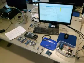
This goal in mind, I implemented my own solution using, well what else than Raspberry Pi 3. I guess Arduino fits to plans, as well. Raspberry Pis can simulate power button press via GPIO pins. I ended up to use a Raspberry Pi 3 with 4 relay module, power button and green power led attached. Only the relay module is used to control server computer power state. In the picture above, blue (+) and black (GND) wires leaving from the relay module are connected to a server's motherboard corresponding power pins.

Raspberry Pi 3 is connected to WLAN. Necessary network configuration for remote access was carried out.
Leech power from the server
Raspberry Pi 3 needs to be powered on all the time server is running. Implementing a solution is very simple:

Pins 9 (+5 VSB, purple; USB 5V+ red wire) and 5 (GND, black; USB GND brown wire) were used for Raspberry Pi 3 USB power cable, following the AllPinouts 24-pin power connector layout schema.
Details
Raspberry Pi 3 & relay module connections
The setup is very simple. You need to attach Raspberry Pi 5V GPIO pin to VCC pin of your relay module. Attach any Raspberry Pi's ground (GND) pin to a GND of the relay module. IN_x_ pins on the relay module must be attached to BCM pins of the Raspberry Pi. I ended up to use the following connection schema with 4 relay module:
| Cable color | Relay module pin | Raspberry Pi 3 GPIO pin | pinout.xyz reference number |
|---|---|---|---|
| Red | VCC | 5V | 2 |
| Black | GND | GND | 6 |
| White | IN1 | BCM18 | 12 |
| Orange | IN2 | BCM23 | 16 |
| Yellow | IN3 | BCM24 | 18 |
| Brown | IN4 | BCM25 | 22 |
NOTE: Only BCM18 (White) + 5V (Red) + GND (Black) are actually used in this configuration. Other BCM pins are attached for future needs.
NOTE: Be careful with your setup, as Raspberry Pi 3 has very limited capabilities of handling different voltages. You should read Raspberry Pi Stack Exchange question What are the min/max voltage/current values the gpio pins can handle? for more information.
You can use pinout.xyz website to find out GPIO pin roles on Raspberry Pis when configuring your setup.
Server computer & relay module connections
If you use relay module pin IN1 (or any IN_x_ pins), attach your server's power wires (+ and GND) to the corresponding relay channel sockets (~referring to those blue “boxes” and their screwable sockets (3 in each) on the relay chip). As I use _IN1_, I attach the server power wires as seen in the picture above. Once relay is activated by Raspberry Pi, it creates a short circuit between server's power GND and power + wires, resulting in powering up/down the server. Basically, we programmatically do just the same than you would otherwise do by hand.
The code
As you know, the mentioned setup doesn't work without code. On your Raspberry Pi 3, you need Python 3 and Python 3 Raspberry Pi GPIO libraries. Once installed, do the following.
On my configuration, I used Python 3 code developed by Samer Afach. As I use BCM18, my setup slightly differs, and the actual code I use is as follows:
> cat /usr/local/bin/server_powerswitch 1#!/usr/bin/env python
2# Source: https://blog.afach.de/?p=436
3
4import RPi.GPIO as GPIO
5import time
6import argparse
7GPIO.setwarnings(False)
8
9#initialize GPIO pins
10GPIO.setmode(GPIO.BCM)
11
12#use command line arguments parser to decide whether switching should be long or short
13#The default port I use here is 18.
14parser = argparse.ArgumentParser()
15parser.add_argument("-port", "--portnumber", dest = "port", default = "18", help="Port number on GPIO of Raspberry Pi")
16
17#This option can be either long or short. Short is for normal computer turning on and off, and long is for if the computer froze.
18parser.add_argument("-len","--len", dest = "length", default = "short" , help = "Length of the switching, long or short")
19args = parser.parse_args()
20
21#initialize the port that you'll use
22GPIO.setup(int(args.port), GPIO.OUT)
23
24#switch relay state, wait some time (long or short) then switch it back. This acts like pressing the switch button.
25GPIO.output(int(args.port),False)
26if args.length == "long":
27 time.sleep(8)
28elif args.length == "short":
29 time.sleep(0.5)
30else:
31 print("Error: parameter -len can be only long or short")
32GPIO.output(int(args.port),True)Naturally, you need to do chmod u+x /usr/local/bin/server_powerswitch after which the power switch command is available on your Raspberry Pi 3 as server_powerswitch and you can power on/off the server via Raspberry Pi 3. Use server_powerswitch --len long for hard power off in a case you have completely lost contact to the server (be aware of data corruption!).
 Emergency control for servers
